Cooling Lab / Engineering guide
Cold Plates: From Heat Load to Hardware
A cold plate is not just a metal block with water running through it. It is a heat-spreading structure, a fluid network, and a mechanical interface that must work together.
By Anagh Dave
Explore a real cold plate in detail, or compare rolled-tube, exposed-tube, and friction-stir-welded products.
1. Follow the heat, not just the water
The heat path is device → package or lid → thermal interface material (TIM) → cold-plate base → coolant. For direct-die cooling, the lid is absent. Heat conducts through the solids and TIM, spreads within the plate, and transfers from the channel walls to the moving liquid by convection.
The liquid leaving the plate is warmer than the liquid entering it. A radiator, liquid-to-liquid heat exchanger, or chiller must remove that energy before the coolant returns. A pump alone does not cool the liquid; it supplies the pressure rise needed to circulate it and adds some heat of its own. A CDU may transfer heat to a facility-water circuit rather than actively refrigerate the coolant. [1]
2. Define the problem before drawing channels
A wattage alone is not a sufficient specification. The same 300 W spread across a large module or concentrated in a small die creates very different spreading and local heat-flux challenges.
- Heat load and map: steady and transient power, source footprint, hot-spot locations, and how much heat actually enters the plate rather than the PCB or surrounding air.
- Temperature budget: maximum permitted junction or case temperature, worst-case inlet temperature, and the package/TIM contribution between that limit and the plate.
- Fluid and hydraulic budget: coolant composition, operating temperature range, available branch flow and differential pressure, and minimum flow during faults or control changes.
- Mechanical envelope: component height tolerance, contact area, keep-outs, fittings, allowable package load, flatness, mass, and service access.
- Lifetime requirements: working pressure, pressure transients, leak criteria, cleanliness, coolant maintenance, corrosion control, and assembly/replacement cycles.
Write the boundary conditions down before comparing supplier curves. A plate characterized on a uniformly heated block is not automatically qualified for a smaller, nonuniform chip.
3. Construction determines more than conductivity
Manufacturing method and channel geometry are related, but not identical categories: a microchannel core can sit inside a brazed or bonded assembly. Select both the heat-transfer structure and a process that can reliably seal it.
A real cold plate, up close
The Wakefield Thermal 120456 is an exposed-tube, four-pass cold plate. This larger manufacturer photograph makes the copper routing and mounting face visible without removing a lid or inventing an internal cutaway.

Blue arrows follow an illustrative inlet-to-outlet route through all four passes in series. Orange arrows show heat entering the contact face from the device and TIM, neither of which is pictured. Heat conducts through the plate and tube wall, then transfers to the coolant by convection; it is not restricted to the few locations marked by arrows.
The inlet/outlet choice is illustrative, not a supplier-specified connection direction. Confirm the permitted plumbing arrangement with the manufacturer. Arrow lengths and colors do not represent measured velocity, temperature, or heat flux.
- Aluminum mounting face
- The broad face supports the heat source and spreads heat toward the coolant path. The source footprint, TIM, and mounting load determine which areas make useful thermal contact.
- Four exposed copper runs
- The straight copper strips are tube walls exposed at the contact face. They bring the source interface closer to the coolant without requiring all heat to first pass through the aluminum spreader.
- Three return bends
- The U-shaped bends connect successive runs into one four-pass route. These are not four independent parallel channels; coolant follows the tube from one connection to the other.
- Two tube connections
- The projecting open ends connect to the external loop. The photograph alone does not specify an inlet direction, fitting arrangement, or allowable hose load; use the supplier's integration guidance.
What off-the-shelf cold plates look like
These are real catalog products, not concept designs. The supplier images show three different approaches to packaging the coolant path. Catalog availability does not guarantee current stock or suitability for a particular device; use the linked product pages for drawings, specifications, and availability.

The copper bends and projecting tube ends make the routed-tube construction visible. The mounting face spreads heat toward the coolant path.
Product photo: Wakefield Thermal, linked from its catalog.
Four tube runs are exposed at the mounting surface, shortening the path from the heat source to the tube wall. TIM contact and surface flatness still matter.
Product photo: Wakefield Thermal, linked from its catalog.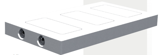
A standard aluminum cold plate with a friction-stir-welded closure. Unlike the exposed-tube example, its coolant passages are enclosed within the body.
Product rendering: Wakefield Thermal, linked from its catalog.Images remain hosted by their respective suppliers; linked catalog pages provide the source if an image becomes unavailable. These examples illustrate construction, not a performance ranking, endorsement, or claim of hands-on testing. Images are not shown to a common scale.
| Construction | Why use it? | What can limit it? |
|---|---|---|
| Tube-in-plate | A formed tube is embedded in a spreader. The tube defines the wetted material; routing can cover a broad module footprint. | Spreading distance to the tube and tube-to-plate contact resistance. Verify tube retention, contact quality, and bend restrictions. |
| Drilled passages | Intersecting drilled bores provide comparatively simple flow paths through a solid block. | Bore placement and available wetted area constrain cooling near small hot spots. Cross-hole plugs and port seals need qualification. |
| Machined channels + sealed lid | Flexible routing, including serpentine paths and parallel channels, with a welded, brazed, bonded, or gasketed closure. | Channel/base tolerances, distortion during joining, lid strength, and leak integrity. Closure method must suit the pressure and coolant. |
| Fin or pin-fin core | Internal extended surfaces add wetted area and can promote mixing. Cores may be brazed, skived, machined, or otherwise formed. | Fin efficiency, bypass flow, joining quality, and pressure loss. More metal surface is only useful if heat and coolant reach it. |
| Microchannel core | Small passages place substantial heat-transfer area close to a concentrated source. | Distribution, filtration, debris tolerance, and fabrication control. Pressure drop depends on the entire geometry and flow, not the name alone. |
A thinner base shortens the through-thickness conduction path but reduces stiffness and may limit lateral spreading. A thicker base can spread a localized load more effectively while adding conduction resistance and mass. The right thickness depends on the source map, channel spacing, pressure, and mounting loads.
4. Route coolant to the heat, not just through the plate
Serpentine paths force flow through one continuous route and avoid channel-to-channel flow splitting, but the coolant warms along the path and long passages and turns consume pressure. A downstream device may see warmer coolant than an upstream one.
Parallel channels shorten individual paths and can reduce hydraulic resistance, but introduce an inlet and outlet distribution problem. Flow divides according to branch resistance and manifold pressure, not simply by channel count. An oversized bypass gap can carry substantial flow while doing little useful cooling.
Split-flow or impinging layouts can deliver fresh coolant near a hot region and shorten the heated flow length. Their benefit depends on inlet placement, distribution, exit routing, and local losses; they are not automatically superior at the same pump power.
5. Separate coolant heating from surface temperature
First: how much does the liquid warm up?
For steady, single-phase flow with approximately constant properties:
Q = ṁ cp (Tout − Tin), ṁ = ρ V̇
Here Q is heat transferred to the liquid in watts, ṁ is mass flow in kg/s, cp is specific heat in J/(kg·K), ρ is density in kg/m³, and V̇ is volumetric flow in m³/s. Temperatures are bulk-fluid inlet and outlet measurements. Use the properties of the actual coolant mixture at the relevant temperature, not water values for every fluid.
This energy balance predicts coolant temperature rise, not chip temperature. A poorly mounted plate can have an acceptable outlet temperature while the device overheats.
Second: how far above the coolant is the surface?
Rb,in = (Tb − Tin) / Q
This defines base-to-inlet thermal resistance in K/W, numerically equivalent to °C/W for temperature differences. Tb must be identified: an area-average base temperature, maximum base temperature, or a specified sensor reading will give different results. State the heat footprint, flow, coolant, inlet temperature, and whether the test includes TIM.
Junction-to-coolant resistance includes more than the plate. It can include the package, lid, TIM, and contact resistances. Do not compare that number with a plate-only base-to-coolant value. Nor should a datasheet junction-to-case metric be added blindly: its test boundary conditions and heat-flow assumptions must match the application. [3]
6. Match thermal performance to the available pump
Read two curves together: thermal resistance versus flow, and pressure drop versus flow, using the intended fluid and temperature. Higher flow reduces bulk coolant warming and often improves convection, but gains may diminish as conduction or interface resistance dominates. In some fully developed laminar regimes, the heat-transfer coefficient changes little with flow.
The operating flow is where the pump's pressure-rise curve intersects the complete system pressure-loss curve. Include the plate, tubing, fittings, quick disconnects, filters, manifolds, and heat exchanger. A pump's free-flow rating is not the flow through an assembled loop.
Phydraulic = Δploop V̇ ; Pelectrical = Phydraulic / η
Use pressure in Pa and volumetric flow in m³/s to obtain watts. Here η is the combined electrical-to-hydraulic efficiency at the actual operating point, not an assumed universal pump efficiency. Plate-only pressure drop gives plate-associated hydraulic power, not total pump demand.
In a series path, the same flow passes through each element and pressure drops add; coolant warms successively across heated plates. Parallel branches share the available differential pressure but may receive different flows. Balancing a branch can improve distribution while increasing the required pump pressure.
7. Worked example: a 300 W heat source
Assumptions: all 300 W enters one cold plate at steady state. Water enters at 25 °C at 1.5 L/min. Use rounded water properties ρ = 1000 kg/m³ and cp = 4180 J/(kg·K). These values support a hand calculation, not a coolant specification.
A. Convert flow and calculate coolant rise
V̇ = 1.5 × 10⁻³ / 60 = 0.000025 m³/s
ṁ = 1000 × 0.000025 = 0.025 kg/s
ΔTcoolant = 300 / (0.025 × 4180) ≈ 2.87 K
Tout ≈ 27.87 °C
B. Estimate a source-surface temperature, not a junction temperature
Suppose characterization for this same footprint, fluid, and flow gives base-to-inlet resistance Rb,in = 0.050 K/W, excluding TIM. Suppose an effective source-surface-to-base interface resistance of 0.015 K/W also applies at the specified clamp load and bond line. These are assumed example inputs, not measured results or typical product ratings. Treat the source and base as approximately isothermal nodes so the series-resistance model is meaningful.
Tb = 25 + 300 × 0.050 = 40.0 °C
Tsource surface = 40.0 + 300 × 0.015 = 44.5 °C
This does not predict maximum die-junction temperature. Package resistance, nonuniform heat generation, local spreading, and sensor locations require a suitable model or measurement. The 2.87 K outlet rise is not added again because Rb,in already uses the inlet reference.
C. Account for pumping power
Suppose the entire loop requires 40 kPa at that flow, with combined pump/motor efficiency η = 0.30.
Phydraulic = 40,000 × 0.000025 = 1.00 W
Pelectrical = 1.00 / 0.30 ≈ 3.33 W
The heat-rejection device must support the 300 W load plus heat entering the coolant from the pump and other sources while maintaining the assumed inlet temperature. Its required capacity depends on the ambient or facility-water conditions, not just the cold plate.
D. What if flow is cut in half?
At 0.75 L/min, the same heat load gives approximately 5.74 K of bulk coolant rise. But do not reuse 0.050 K/W without a resistance-versus-flow curve. Convection and flow distribution may change, so doubling the coolant rise does not by itself predict the new source temperature.
8. The plate is only as good as its interfaces
TIM, flatness, and clamp load
A high-performance channel core cannot compensate for a poor contact patch. Control base flatness, surface finish, parallelism, TIM coverage, and bond-line thickness at the assembled condition. Thermal expansion and internal pressure can deform a plate that looks flat before mounting.
Set clamp load from package limits and the TIM's compression/contact requirements, not from a universal torque value. Fastener torque is only an indirect estimate of preload; friction and the load path matter. Check load distribution, hard stops, screw sequence, and fitting or hose forces that can tilt the plate.
Assembly motion matters too. A robotic end effector that swivels after contact can shear or displace TIM. Finish orientation before loading the interface where practical, and verify both engagement and release. See the TIM material and failure-mode guide and the robotic cold-plate engagement case study.
Materials and coolant are a system-level choice
Copper offers greater thermal conductivity than common aluminum alloys but adds mass and cost. Aluminum can be attractive for weight and manufacturing. Neither choice guarantees compatibility: inventory every wetted material, including tubes, braze alloys, coatings, fittings, seals, and the heat exchanger.
Galvanic corrosion requires dissimilar materials, electrical coupling, and an electrolyte; mixed-metal loops need deliberate compatibility and coolant-chemistry control. A coating is not a substitute for evaluating defects and long-term exposure. Deionized water does not stay ion-free in service and is not a blanket corrosion or electrical-safety solution.
Glycol concentration changes freezing protection, viscosity, heat capacity, and conductivity, affecting both curves used for selection. Confirm elastomer compatibility and an approved maintenance plan with the coolant and hardware suppliers. Select filtration for the smallest passages and contamination sources, including assembly debris, without consuming the hydraulic margin. If surfaces can fall below the local dew point, address condensation as well as cooling performance.
9. Validate the assembly, not just a CFD image
Use conjugate heat-transfer analysis to examine solid conduction and fluid convection together. Include the actual heat map, manifolds, interface assumptions, fluid properties, and relevant tolerances. Check mesh independence and conservation of mass and energy, then correlate temperature and pressure predictions against a controlled bench test.
| Observation | Possible mechanism | Useful check |
|---|---|---|
| High device temperature, normal bulk flow | Poor TIM contact, local flow starvation, or a changed power map. | Compare local temperatures and interface condition at a controlled load; inspect for bypass and distribution errors. |
| Higher pressure drop at the same flow and fluid temperature | Debris, fouling, or a restriction in the measured section. | Localize pressure measurements, inspect filters/passages, and verify coolant concentration and sensor calibration. |
| Unstable temperatures or flow after filling | Trapped gas, inadequate bleeding, or pump inlet problems. | Check fill/bleed procedure, orientation, reservoir level, and pump inlet conditions. |
| Performance drifts after repeated mounting | TIM displacement, preload variation, base damage, or package/plate warpage. | Track contact condition, bond line, and mounting repeatability, including rotation and release. |
| Leaks or corrosion products over time | Seal incompatibility, joint defects, corrosion, or pressure/thermal fatigue. | Inspect the affected joint and fluid chemistry; qualify the complete wetted assembly across its specified life conditions. |
A useful qualification record includes
- Thermal measurements: calibrated inlet/outlet sensors, local source/base temperatures, coolant flow, and electrical heat input after stabilization. Compare Qfluid = ṁcpΔT with input power while accounting for heat losses and uncertainty. A small liquid temperature difference can make sensor mismatch significant.
- Hydraulic measurements: pressure taps defining exactly what is included, curves over the specified coolant/temperature range, and the operating point with production hoses, fittings, and filters.
- Mechanical and fluid integrity: leak checks, proof-pressure and life testing to an approved specification, mounting cycles, and inspection for deformation or joint damage. Proof pressure and allowable leakage are application-specific, not universal multipliers.
- Off-nominal conditions: warm inlet coolant, reduced or lost flow, partial restriction, orientation, and pump/control faults, with suitable overtemperature protection rather than relying on a steady-state estimate.
- Repeatability and aging: multiple assemblies, TIM variation, coolant exposure, and relevant pressure/thermal cycles. Report uncertainty and degradation, not only the best initial temperature.
10. References and further reading
Manufacturer resources provide system context and examples of published performance data. They are not evidence that the illustrative calculation above describes a particular commercial plate.
- CoolIT Systems: Coldplate Technology — the cold plate's role as the point of heat capture within a larger cooling system.
- CoolIT Systems: Liquid Cooling Product Technology — CDUs, distribution systems, monitoring, and controls.
- Texas Instruments: Semiconductor and IC Package Thermal Metrics — interpretation and limitations of package thermal metrics.
- Boyd: Liquid-Cooled Cold Plates technical datasheet (PDF) — further reading on construction options and supplier performance information; confirm current specifications before selection.